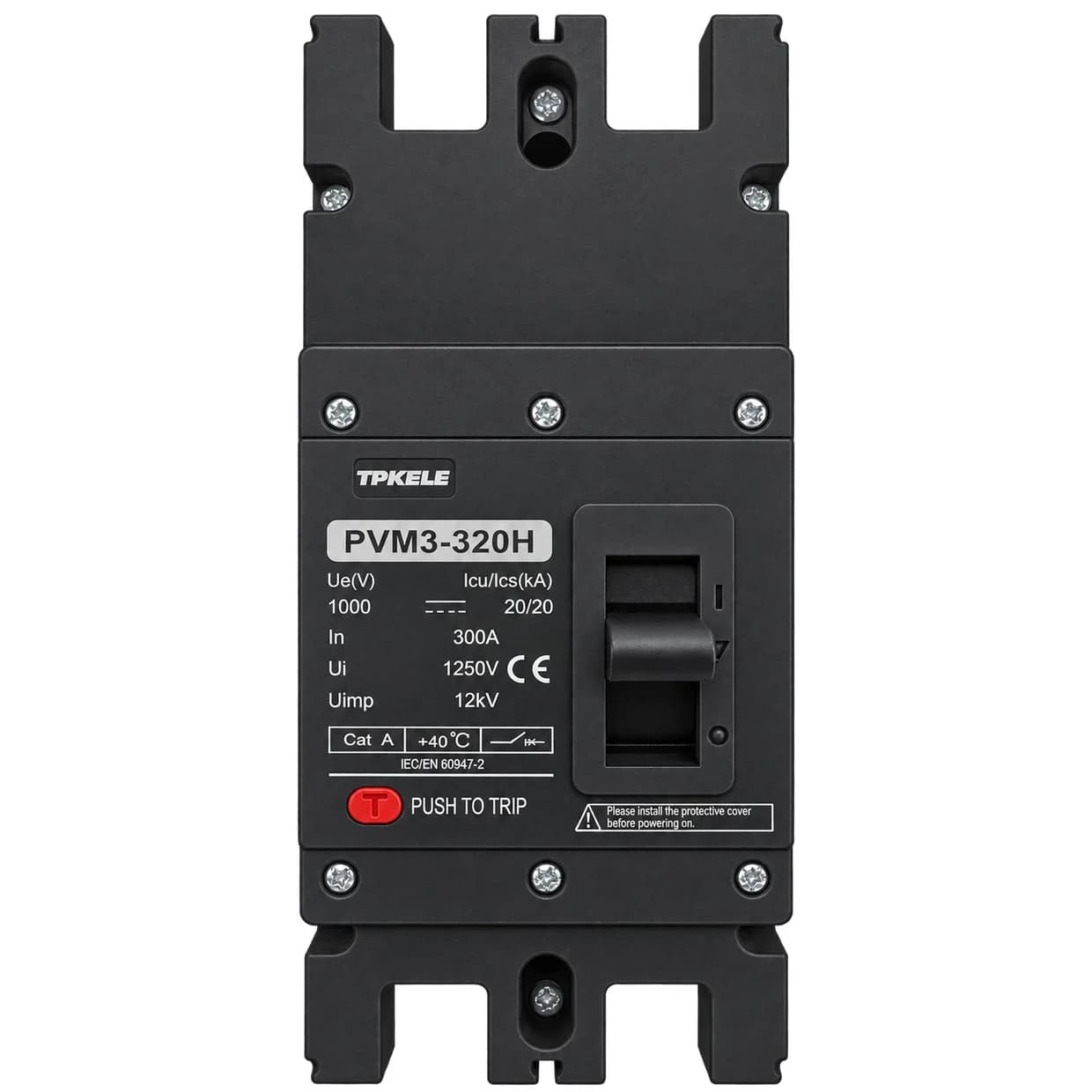
MCCB
DC MCCB PVM3 Series
TPKELE PVM3 DC MCCB is a molded case circuit breaker for high-current DC circuits, with 250A to 800A frame sizes, 1000V / 1250V / 1500V DC working voltage options and 20kA breaking capacity. It provides overload and short-circuit protection and isolation, and protects PV modules from dangerous reverse DC current.
Key Features
- 250A–800A frames: 250H / 320H / 400H / 630H / 800H
- 1000V / 1250V / 1500V DC working voltage options
- Icu = Ics = 20kA, total breaking time 20ms
- Zero-arc design, arcing distance ≥50mm
- Isolation function, protects PV modules from reverse DC current
Need full datasheet, drawing or certificates for tender?
Typical Applications
PVM3 DC MCCB Model Selection
| Model | PVM3-250H | PVM3-320H | PVM3-400H | PVM3-630H | PVM3-800H |
|---|---|---|---|---|---|
| Frame current Inm (A) | 250 | 320 | 400 | 630 | 800 |
| Rated current In (A) | 125, 140, 160, 180, 200, 225, 250 | 280, 315, 320 | 315, 350, 400 | 400, 500, 630 | 630, 700, 800 |
| Poles | 2P / 3P | 2P / 3P | 4P | 4P | 4P |
| Rated working voltage Ue (V DC) | 1000 (2P) / 1250 (3P) / 1500 (3P) | 1000 (2P) / 1250 (3P) / 1500 (3P) | 1000 / 1250 / 1500 | 1000 / 1250 / 1500 | 1000 / 1250 / 1500 |
| Rated insulation voltage Ui (V) | 1000 (2P) / 1500 (3P) | 1000 (2P) / 1500 (3P) | 1500 | 1500 | 1500 |
| Overall dimensions L×W×H (mm) | 180×76×126 (2P) / 180×107×126 (3P) | 180×76×126 (2P) / 180×107×126 (3P) | 258×200×107 | 280×280×115.5 | 280×280×115.5 |
Please state the required system voltage, pole count and rated current when requesting a quotation.
PVM3 DC MCCB Common Parameters
| Parameter | Value |
|---|---|
| Standard | IEC 60947-1, IEC 60947-2 (GB/T 14048.1, GB/T 14048.2) |
| Rated impulse withstand voltage Uimp | 12 kV |
| Extreme short-circuit breaking capacity Icu | 20 kA |
| Running short-circuit breaking capacity Ics | 20 kA |
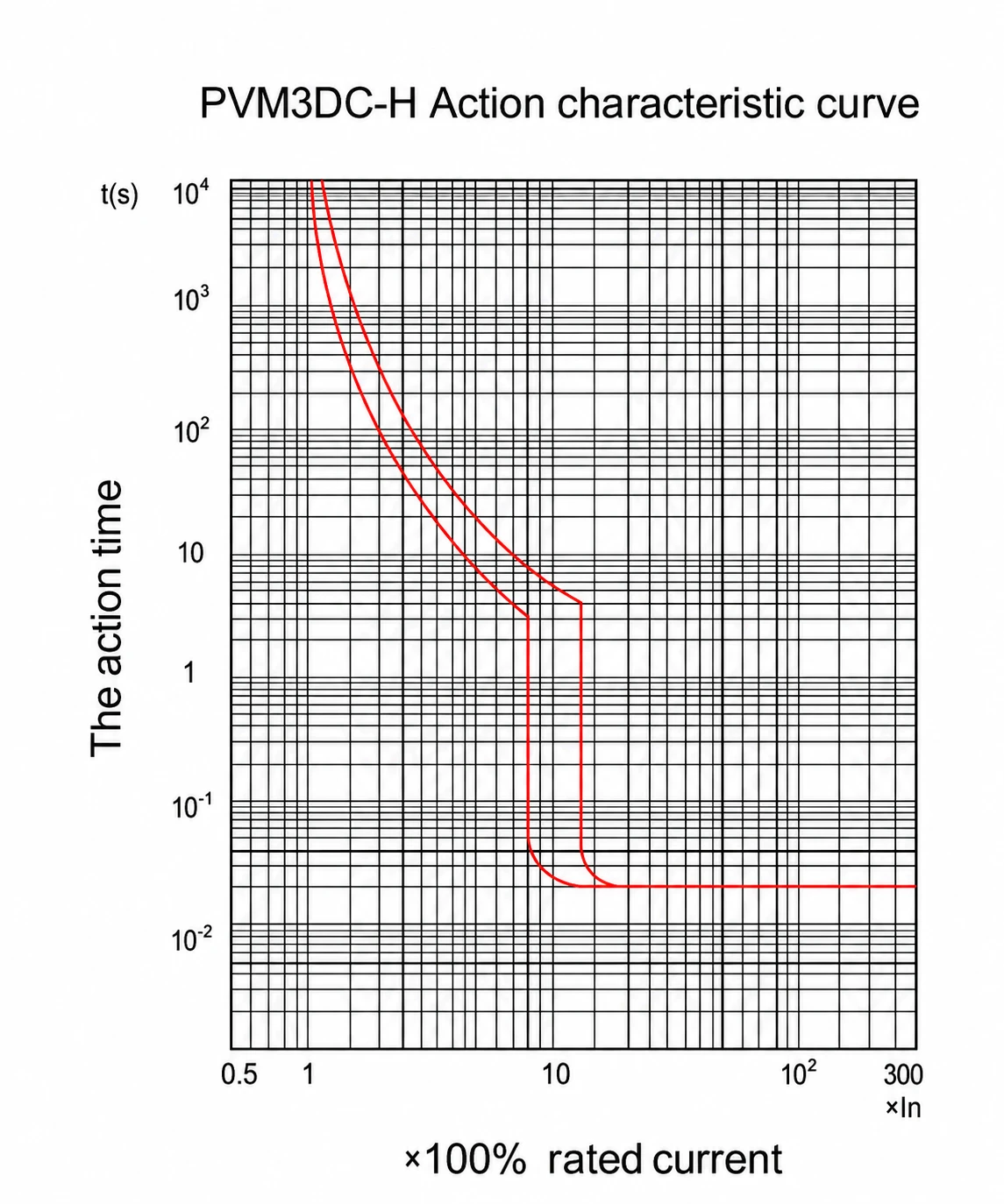
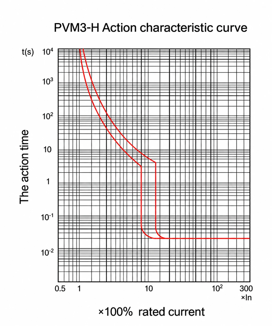
| Transient action value | 10 In |
| Total breaking time | 20 ms |
| Mechanical life | 10,000 operations |
| Electrical life | 2,000 operations |
| Isolation function | Yes |
| Arcing distance | ≥50 mm (zero arc, with arcing cover) |
| Allowable ambient temperature | -40°C to +70°C |
| Degree of protection | IP20 |
| Wiring mode | Incoming line on top, load on bottom |
| Installation | Fixed type, plug-in type |
| Accessories | Auxiliary contact, alarm contact, shunt release, undervoltage release, electric operation |
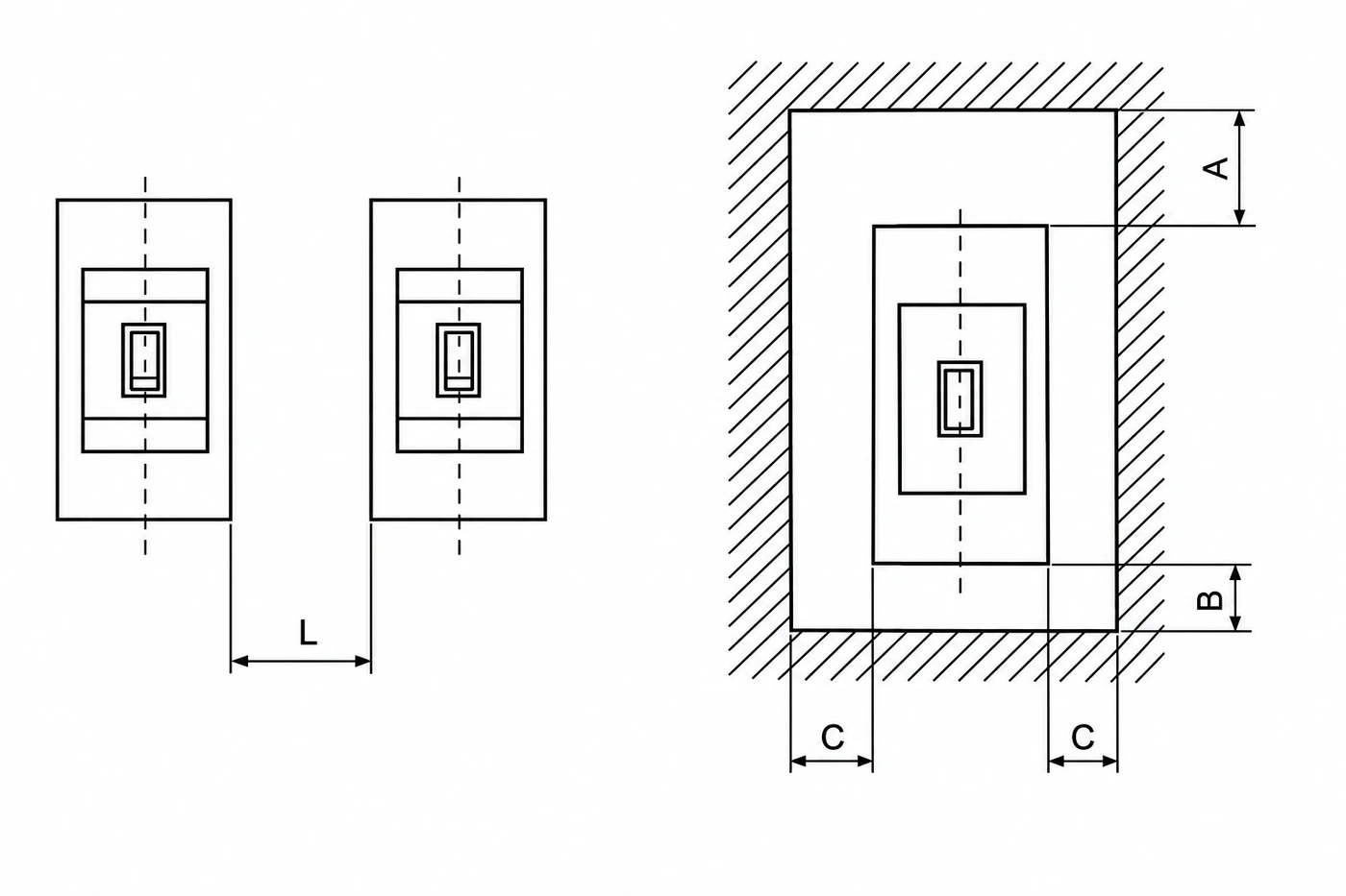
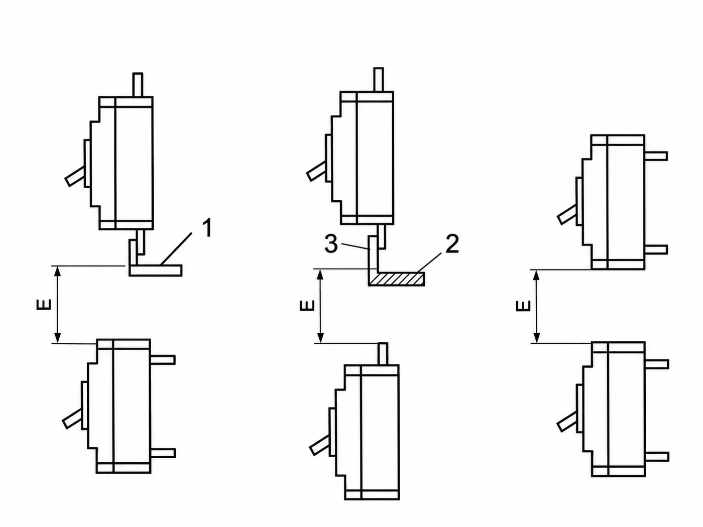
Safe Installation Clearance
| Type | L (mm) | A — no cover (mm) | A — with arcing cover (mm) | B (mm) | C (mm) | E — no cover (mm) | E — with arcing cover (mm) |
|---|---|---|---|---|---|---|---|
| PVM3-250H / 320H | 40 | 50 | 30 | 25 | 25 | 50 | 60 |
| PVM3-400H | 40 | 50 | 30 | 25 | 25 | 50 | 60 |
| PVM3-630H | 70 | 100 | 30 | 25 | 25 | 100 | 60 |
| PVM3-800H | 70 | 100 | 30 | 25 | 25 | 100 | 60 |
L = distance between adjacent breakers; A = clearance above and C = clearance to the side when mounted in an enclosure; B = clearance below; E = clearance below the terminals, with or without the zero-arc cover fitted. Confirm against the panel drawing for your specific frame and accessory combination before fabrication.
Release Type & Accessory Codes
| Accessory Code | Accessory | 250H / 320H (2P, 3P) | 400H–800H (4P) |
|---|---|---|---|
| 200 / 300 | Without inner accessory | — | — |
| 208 / 308 | Alarm contact | Yes | Yes |
| 210 / 310 | Shunt release | Yes | Yes |
| 220 / 320 | Auxiliary contact (1NO1NC) | Yes | — |
| 220 / 320 | Auxiliary contact (2NO2NC) | — | Yes |
| 230 / 330 | Undervoltage release | Yes | Yes |
| 240 / 340 | Shunt release + auxiliary contact (1NO1NC) | Yes | — |
| 240 / 340 | Shunt release + auxiliary contact (2NO2NC) | — | Yes |
| 250 / 350 | Shunt release + undervoltage release | Yes | Yes |
| 260 / 360 | Group 2 auxiliary contact (2NO2NC) | Yes | — |
| 260 / 360 | Group 2 auxiliary contact (4NO4NC) | — | Yes |
| 270 / 370 | Undervoltage release + auxiliary contact (1NO1NC) | Yes | — |
| 270 / 370 | Undervoltage release + auxiliary contact (2NO2NC) | — | Yes |
| 218 / 318 | Shunt release + alarm contact | Yes | Yes |
| 238 / 338 | Undervoltage release + alarm contact | Yes | Yes |
| 248 / 348 | Shunt release + auxiliary contact + alarm contact | Yes | Yes |
| 278 / 378 | Group 2 auxiliary contact + undervoltage release + alarm contact | Yes | Yes |
Accessory availability and pole combinations vary by frame size. Please confirm the exact code with your order — state frame size, pole count and required accessory function in the inquiry.
Technical Diagrams
Certifications & Standards
Verified to international standards for global tenders
OEM / ODM Available
Private label this MCCB for your brand
Logo, color housing, packaging and certificate documentation tailored to distributor and brand-owner programs.
- Custom logo printing on housing and packaging
- Color housing variants for product line differentiation
- Private-label catalogs and datasheet customization
- Project-spec drawings, single-line diagrams and labels
- Container-load supply with export documentation
- Sample preparation within 5–10 working days
Frequently Asked Questions
When should I use a DC MCCB instead of a DC MCB?
DC MCBs on DIN rail cover currents up to 125A. Above that, such as PV array main circuits and battery bank disconnects, a molded case breaker with a higher frame size (250A–800A) and higher breaking capacity is the usual choice.
What DC voltages does the PVM3 series support?
Each frame is offered with 1000V, 1250V and 1500V DC working voltage options. 250H and 320H frames come in 2P and 3P versions; 400H, 630H and 800H frames are 4P.
What is the breaking capacity?
Extreme and running short-circuit breaking capacity (Icu and Ics) is 20kA for the series, with a total breaking time of 20ms. Please confirm the value for your system voltage when requesting a quotation.
Which accessories are available?
Auxiliary contacts, alarm contacts, shunt release, undervoltage release and electric operation. Available combinations depend on frame size and pole count, so please state your configuration in the inquiry.
How do the auxiliary and alarm contacts work?
The auxiliary contact (terminals F11-F14, F21-F24) follows the breaker position: closed when the breaker is ON, open when it is OFF, for remote status indication. The alarm contact (terminals B11-B14) switches when the breaker trips on a fault — it stays in its normal state for a manual OFF, and changes state on a 'free trip' (automatic) opening, so it can be wired to a fault alarm separately from normal switching. Rated 220V AC, 3A.
How should the breaker be connected?
The series is wired with the incoming line on the top terminals and the load on the bottom terminals. A protective cover must be installed before powering on.